CAN lower layer
This specification defines layer 3 (Network) and 4 (Transport) of the ThingSet Protocol via CAN bus. Layer 1 and 2 are provided by the CAN bus itself.
Only the binary messages of the ThingSet Protocol are supported via CAN.
General features
Master-less operation
Automatic node ID assignment
Efficient useage of CAN ID and data bytes
Transport protocol to allow payload of more than 8 bytes
Two different types of messages for application layer
- Service message (request/response)
- Data object publication message (publish/subscribe)
RTR frame is not allowed
Fixed bitrate of 250 kbit
CAN identifier layout
In the CAN bus, the identifier part of the CAN frame is used for arbitration and identification of the message type. Typically, it does not define the sender or receiver of the message, but the content of the message.
For a network with connected ThingSet devices, the layout of the CAN identifier is similar to the SAE J1939 specification. Parts of the identifier define the source and destination address of the message. In addition to that, the first three bits are used to prioritize the messages.
Two general types of messages are specified: Service message and Data object publication message. Only CAN extended ID with a size of 29 bit is used.
Service message
A service message is used for the request/response communication model. A single byte each for source and destination node address are defined as part of the CAN ID to identify sender and receiver of the message. In addition to that, the function ID is specified as part of the CAN ID.
CAN identifier layout
The service message CAN ID layout is shown in the following picture:
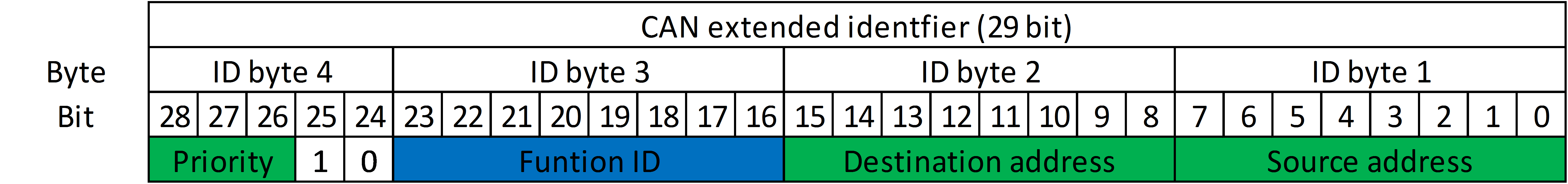
- Priority (28-26): Defines the importance of the message. For service messages, only 3 (high priority) or 7 (low priority) are valid.
- Extended data page / EDP (25): Always 1b to prevent collision with SAE J1939 and NMEA2000 devices on the same bus
- Message type (24): 0b for service message
- Function ID (23-16): Function ID of application layer protocol
- Destination address (15-8): Destination node address (255 for broadcast)
- Source address (7-0): Source node address (255 for anonymous message during address claiming)
Transport protocol (ISO 15765-2)
In order to transfer data with a length of more than 8 bytes, the transfer protocol specified in ISO 15765-2 (ISO-TP)open in new window is used.
It allows a maximum number of 4095 data bytes (defined by 12 bit unsigned int length code in first frame). Flow control mechanisms ensure the reliability of data reception.
As a very important feature, ISO-TP allows the efficient transfer of single-frame messages with only one byte of overhead (and no flow control packets). This feature is necessary, as it is not known before if a certain function of the energy management protocol will transfer only a few bytes or a large amount of data.
Unfortunately, the standard is not accessible for free. However, several open source implementations (including SocketCAN for Linuxopen in new window) of the ISO-TP are available. Most important information about the frame layout can be found on Wikipediaopen in new window.
Single-frame message request/response
Application protocol data of 8 bytes or lower can be transferred using a single CAN frame. The function ID of the application protocol (byte 1) is already included in the CAN indentifier. The first byte of the CAN data contains the ISO-TP header for a single-frame message. Bytes 2 to n (with n <= 8) are contained in the remaining data bytes of the CAN frame.
| Byte 1 | Byte 2 | ... | Byte 8 |
|---|---|---|---|
| ISO-TP header | Application protocol (byte 2) | ... | Application protocol (byte 8) |
Multi-frame message request/response
More than 8 bytes of application protocol data are sent as multi-frame messages.
The first message contains two bytes for the ISO-TP header (including also the total message length). As the function ID (first byte of application protocol data) is already stored in the CAN identifier, the application protocol byte numbering starts with 2.
| Byte 1 | Byte 2 | Byte 3 | ... | Byte 8 |
|---|---|---|---|---|
| ISO-TP header | Application protocol (byte 2) | ... | Application protocol (byte 7) | |
Consecutive messages i = 2...585 consume only one byte for the ISO-TP header:
| Byte 1 | Byte 2 | ... | Byte 8 |
|---|---|---|---|
| ISO-TP header | Application protocol (byte i\*7-6) | ... | Application protocol (byte i\*7) |
Remarks regarding existing transport protocols
Several other transport protocols for CAN have been defined in different standards.
For the J1939 protocol, the transport protocol is specified in the standard SAE J1939-21. Two types of transport protocol are defined: The Connection Mode Data Transfer (CMDT) and the Broadcast Announce Message (BAM). CMDT is used to exchange data between two nodes. It includes methods for flow control and handshake. BAM is more simple and broadcasts a multi-packet message to the bus without feedback if the message was received.
CMDT and BAM allow to transfer 9 to 1785 bytes (255 packets * 7 bytes) of payload. It is not allowed to transfer 0 to 8 bytes using the J1939 transport protocols. Thus, we need to know before if a message needs the mechanisms of the transport protocol or not. This is not possible for the flexible energy management protocol, as the same functions might transfer either very little data (e.g. write 16-bit integer) or a large amount of data (e.g. write a strings). Data with less than 9 bytes would have to be stuffed, making the protocol very inefficient. A message which could fit into a single CAN frame would need 5 frames (including flow control) when using CMDT and stuffing.
The RV-C standard defines a different transport protocol than SAE J1939, which also allows the transfer of up to 1785 bytes. However, is does not specify any flow control mechanisms at all. So it is not possible to determine if a message was received even for a communication between only two nodes, which is not acceptable.
NMEA 2000 uses the same transport protocol as the SAE J1939 protocol. In addition to that, it defines a so-called fast packet protocol. With NMEA 2000 fast packet protocol, 223 bytes can be transferred without flow control, thus, making it more efficient and "fast".
With the fast packet protocol, a single frame transfer is possible. However, a single frame message consumes 2 out of 8 bytes for the fast packet header information. This is considered too high overhead if it is unknown whether a single or multi-frame message has to be used. The Tiny-TP (see below) for the data object publication messages is based on the NMEA 2000 fast packet protocol, but reduces its overhead for single frame messages.
Overview of different CAN based transport protocols:
| ISO-TP | NMEA 2000 fast packet | SAE J1939-21 | RV-C | |
|---|---|---|---|---|
| Number of data bytes | 0..4095 | 0..223 | 9..1785 | 9..1785 |
| Flow control | yes | no | yes | no |
| Efficient single frame | yes | no | no | no |
| Open standard | no | no | no | yes |
Data object publication message
CAN identifier layout
Publication messages are not sent to a single node, so the destination address does not need to be specified. So, instead of the function ID byte and the destination address byte, the data object ID is specified in the CAN identifier to have more bytes available for payload in the data bytes.
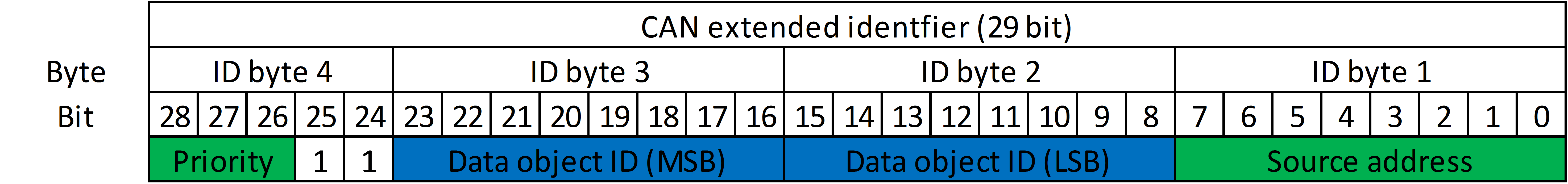
- Priority (28-26): Defines the importance of the message. For data object publication messages, only 4 (high priority), 5 (medium priority) and 6 (low priority) are valid.
- Extended data page / EDP (25): Always 1b to prevent collision with SAE J1939 and NMEA2000 devices on the same bus
- Message type (24): 1b for data object publication message
- Data object ID (23-8): Data object ID of application layer protocol which is published. The most significant byte of this 16-bit ID is stored first (bits 23 to 16).
- Source address (7-0): Source node address (255 for anonymous message during address claiming)
CAN data format
Data type and content
The first byte of the payload defines the data type of the published data object. The data type is encoded using a 6-bit unsigned integer. The first two bits of the byte can be used for other purposes (see below).
The following data types are defined:
| 6-bit typeID | CBOR type | CBOR description |
|---|---|---|
| 0x00 | 0x18 | Unsigned integer (one-byte uint8_t follows) |
| 0x01 | 0x19 | Unsigned integer (two-byte uint16_t follows) |
| 0x02 | 0x1a | Unsigned integer (four-byte uint32_t follows) |
| 0x03 | 0x1b | Unsigned integer (eight-byte uint64_t follows) |
| 0x04 | 0x38 | Negative integer -1-n (one-byte uint8_t for n follows) |
| 0x05 | 0x39 | Negative integer -1-n (two-byte uint16_t for n follows) |
| 0x06 | 0x3a | Negative integer -1-n (four-byte uint32_t for n follows) |
| 0x07 | 0x3b | Negative integer -1-n (eight-byte uint64_t for n follows) |
| 0x08 | 0x58 | byte string (one-byte uint8_t for n, and then n bytes follow) |
| 0x0C | 0x78 | UTF-8 string (one-byte uint8_t for n, and then n bytes follow) |
| 0x10 | 0x98 | array (one-byte uint8_t for n, and then n data items follow) |
| 0x14 | 0xb8 | map (one-byte uint8_t for n, and then n pairs fo data items follow) |
| 0x1E | 0xfa | Single-Precision Float (four-byte IEEE 754) |
| 0x1F | 0xfb | Double-Precision Float (eight-byte IEEE 754) |
| 0x20 | 0xc0 | Text-based date/time (data item follows; see section 2.4.1 |
| 0x21 | 0xc1 | Epoch-based date/time (data item follows; see section 2.4.1 |
| 0x24 | 0xc4 | Decimal Fraction (data item "array" follows; see Section 2.4.3 |
| 0x3C | 0xf4 | False |
| 0x3D | 0xf5 | True |
| 0x3E | 0xf6 | Null |
| 0x3F | 0xf7 | Undefined |
The data type is compatible with the CBOR format used in the ThingSet application layer protocol. The 6-bit data type ID can be converted to a valid CBOR first byte using simple bit-shift operations.
Assuming the data of the CAN frame is stored in an array data[0...7], use the following operation to generate valid CBOR data for type ID < 0x20 (stored in data[0]) :
data[0] = (data[0] & 0x1C) << 3 + (data[0] & 0x03) + 0x18
For data type ID >= 0x20 (stored in data[0]) the bit shifting operation is slightly different:
data[0] = (data[0] & 0x18) << 1 + (data[0] & 0x07) + 0xC0
Of course, you can also store a map of the above table and replace the 6-bit typeID by the CBOR type. However, the bit-shift operations will be more efficient.
Using above method, the generated CBOR might not be the most compact form, as the values stored directly in the first byte (e.g. 0..23) are not used. However, the generated data is still valid CBOR.
Time stamp
In order to acquire real-time measurement values, a 16-bit timestamp (unsigned int) can be appended to the data content bytes. The timestamp contains the 16 least significant bits of the microcontroller's system clock in milliseconds. It is a rolling counter and restarts at 0 after an overflow. The timestamp cannot be used to determine the absolute time of a measurement, but the time difference between subsequent measurements. This is important to obtain correct sampling of time-series data if higher priority messages cause a delay of the data delivery on the bus.
The second bit of the first byte defines if the time stamp is present or not (see below).
Tiny transport protocol (Tiny-TP) for message broadcasting
The transport protocol for the data object publication messages is much more simple and lightweight than the ISO-TP used for the service messages described above.
It fulfills the following requirements:
- Minimum overhead for single-frame messages
- No flow control
- Comparably low maximum data length to allow small buffer sizes
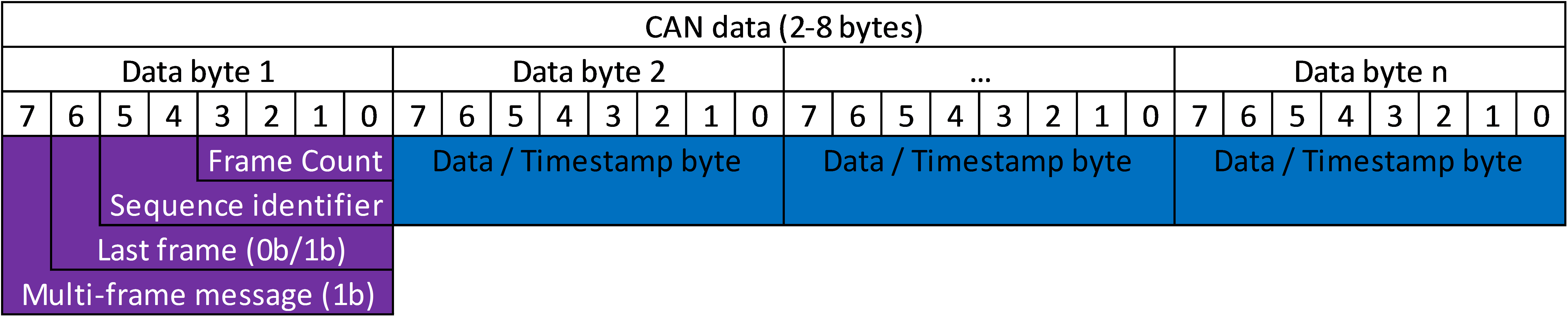
The Tiny-TP adds a header of 1 byte to each message with the following format:
- bit 7: multi-frame message
- bit 6: last frame
- bits 5-4: sequence identifier (2-bit unsigned integer)
- bits 3-0: frame count (4-bit unsigned integer)
For a multi-frame message, bit 7 is set to 1, for a single-frame message to 0. In case of a single-frame message, the remaining 7 bits of the Tiny-TP header might be used as payload data.
The last frame is identified with bit 6 set to 1. For all other multi-frame packets it must be set to 0.
In order to distinguish different messages with the same CAN ID, bits 5-4 contain a sequence identifier which is incremented each time a multi-packet message transfer for the same CAN ID (i.e. data object ID) is started.
The last four bits (3-0) contain a frame counter. The first frame of a multi-frame message starts with the frame counter set to 0. A maximum total number of 16 multi-frame messages is possible, resulting in a maximum of 2^4*7 = 112 bytes maximum message length.
Compared to NMEA 2000 fast-packet, the Tiny-TP format reduces the overhead of single-frame messages from two bytes to as low as 1 bit.
Single-frame data publication message
A single-frame message uses only the first bit of the Tiny-TP. The remaining bits of the first byte are used for a timestamp flag and the data type, thus using the 8 CAN data bytes very efficiently.
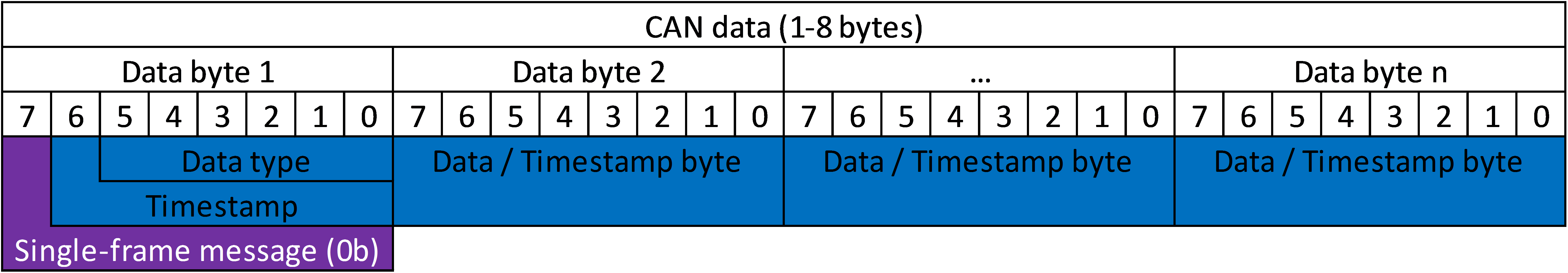
- Multi-frame message flag: 0b (single-frame message)
- Timestamp flag: 1b if timestamp will be sent, otherwise 0b
- Data type: 6-bit unsigned int (see application protocol)
- Data / Timestamp bytes: data bytes depending on data type, 16-bit timestamp appended if timestamp flag set.
Multi-frame data publication message
Multi-frame messages need the entire first byte for the Tiny-TP header information. The timestamp flag and the data type are moved to the second byte, followed by the data content and timestamp (if enabled).
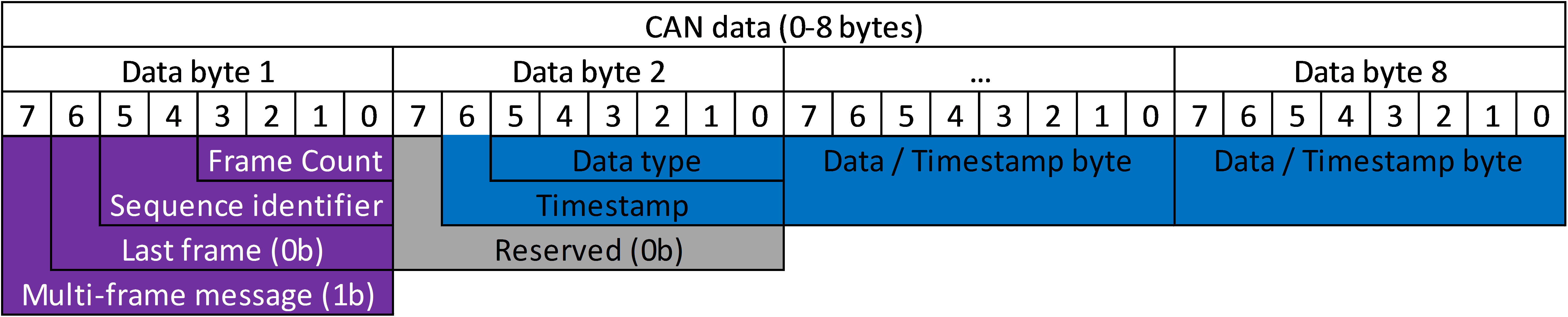
- Multi-frame message flag: 1b
- Last frame flag: 0b
- Sequence identifier: 0-3 (incremented for each start of multi-packet message transmission for given CAN ID)
- Frame count: 0 (first frame)
- Timestamp flag: 1b if timestamp will be sent, otherwise 0b
- Data type: 6-bit unsigned int (see application protocol)
- Data / Timestamp bytes: data bytes depending on data type, 16-bit timestamp appended if timestamp flag set.
Consecutive messages also contain the Tiny-TP header, directly followed by the data / timestamp bytes.
- Multi-frame message flag: 1b
- Last frame flag: 1b if last frame, otherwise 0b
- Sequence identifier: 0-3 (see above)
- Frame count: 0-15
- Data / Timestamp bytes: data bytes depending on data type, 16-bit timestamp appended if timestamp flag set.
CAN Physical layer
ToDo:
- RJ45 connector using CANopen pinout
- Bus Power supply